Home > Electronics > Arduino Compatible SCM & DIY Kits > Arduino Compatible Kits & DIY Kits

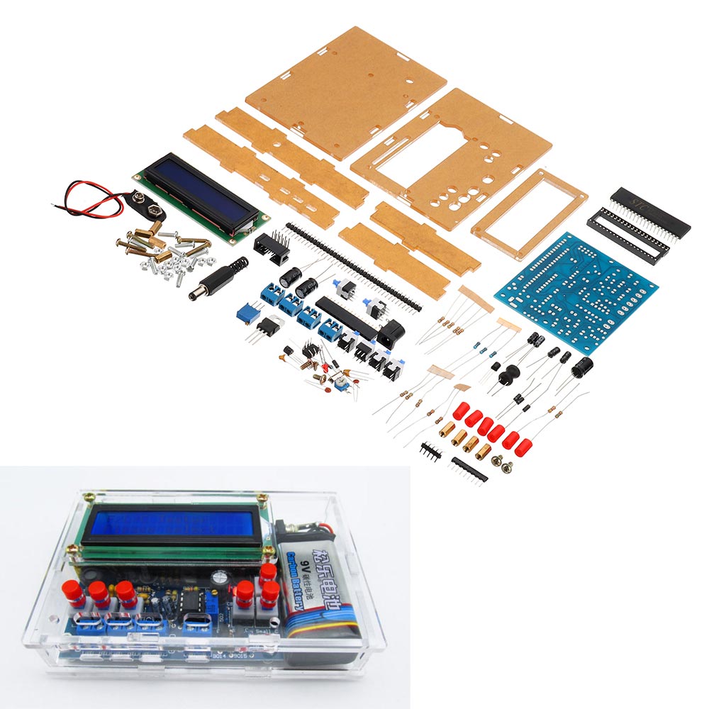
DIY Inductance Capacitance Frequency Meter Tester Kit Based On 51 Single-chip MCU With Shell
Parameter: Board size: 6.8*8.5CM Supply voltage: DC5V or DC8-14V or AC7 to 10V Various gear range instructions: Inductance measurement range: 0.1H--------1H Small capacitance measurement range: 1pF-------2.2F (no polarity capacitor) Frequency measurement range: 20Hz ------400KHz (measured small signal) Electrolytic capacitance measurement range: 0.5F--12000F (electrolytic capacitor) F theoretical frequency measurement 0-500k, sampling error within a few hz, this function can be said to be attached, do not white, but there are certain requirements for the input signal, because the Schmitt trigger is not used, so it is only used to measure common mode Ideal waveform with less interference. Note: When the power is on, the LCD will probably have a white screen of about 2 seconds. This is because the program is designed like this. The system is powered on for 2 seconds. The system calculates some initial references that need to be used for subsequent measurements. The white screen interval is pressed except the power switch. The other switches are required to bounce. If there is a switch hold down, the subsequent measurement data will be inaccurate, remember. After 2 seconds of the white screen, the LCD will display: F/C/L Tester, then you can start measuring the parameters of the component you want. For example, if the non-polarity capacitor is measured, connect the 'non-polarity capacitor test switch' after connecting the non-polarity capacitor. For example, if you measure the inductance, press the 'inductance test switch' after connecting the inductor. The 5 function switches can only be used at the same time. Press one to test what is pressed, and the one that is not used is required to bounce. When non-polar capacitors, inductors, and polar capacitors are tested, these components are connected to the test socket without polarity. The frequency test needs to distinguish the polarity. If it is the first time after the kit is soldered, you need to adjust the contrast of the liquid crystal. After power-on for 2 seconds, adjust the 10K potentiometer on the back of the board to make the display effect of the1602 better. Package included: 1 x PCB board(Not included the Battery) 1 x Shell and screws 1 x 16P pin header 1 x 40P pin straight 1 x Bent pin 2 stitches 1 x LCD1602 1 x 10³ blue and white potentiometer 1 x DC3-10 horn seat 1 x 40P IC block 1 x STC89C52 1 x 8P IC block 1 x LM393 6 x 8*8 self-locking switch 4 x KF301-2P terminal block 1 x DC005 seat 1 x LM7805 1 x A09-103 exclusion 1 x 3296-502 potentiometer 2 x 22P ceramic capacitor 4 x 1N4007 1 x 12M crystal oscillator 3 x 470UF/16V capacitor 4 x 10UF/25V capacitor 1 x 3MM LED 1 x 100UH inductor 2 x 10² monolithic capacitor 1 x 10⁵ monolithic capacitor 1 x 9014 triode 1 x 9015 triode 2 x 10K resistor 5 x 1K resistor 3 x 100K resistor 3 x 2K resistance error 1% 1 x 47K resistor 1 x 5.6K resistor 1 x 100 ohm resistance error 1%