Home > Electronics > Arduino Compatible SCM & DIY Kits > Arduino Compatible Kits & DIY Kits

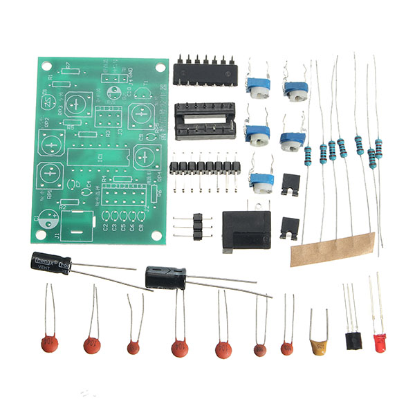
ICL8038 Function Signal Generator Kit Multi-channel Waveform Generated Electronic Training DIY Spare Part
Note: This is a DIY kit, you need to assemble it. Manual: http://img.banggood.com/file/products/20170822044641Manual.pdf Feature: The ICL8038 is a precision oscillating integrated circuit with multiple waveform outputs. The frequency and duty cycle of the output waveform can also be controlled by current or resistance. Since the chip has an FM signal input, it can be used to frequency-modulate low-frequency signals. The kit is designed for the frequency range commonly used, divided into five stalls adjustable, can produce from 10Hz-450KHz low distortion sine wave, triangular wave, square wave pulse signal. Circuit principle: ICL8038 pin function: 1 pin, 12 pin: sine wave adjustment side 2 pin: sine wave output 3 pin: triangular wave output 4 pin, 5 pin: frequency and duty cycle (or waveform asymmetry) adjustment 6 pin: V + positive power supply 7 pin: frequency offset 8 pin: frequency adjustment input 9 pin: square wave output. This is an open collector output. When working, connect a load resistor from the pin to the corresponding positive supply, to obtain a TTL-compatible square wave output, the load resistor must be connected to the + 5V supply. 10 pin: timing capacitor side 11 pin: V- negative power supply terminal connect ground. When using positive and negative power supply, 11 pin connected to the negative power supply, the output waveform is relative to 0V symmetry. When using a single positive power supply, pin 11 is grounded and the output waveform is unipolar and the uniform voltage is + VCC / 2. 13 pin, 14 pin: empty pin The frequency range is 10KHz-450KHz, divided into 5 bands, with switch J2 (short-circuit cap) to switch, PR1 is the frequency adjustment, RP2 is the square wave duty cycle adjustment, RP3 is the square wave linear adjustment, RP4 is the sine wave distortion adjustment, RP5 is the output amplitude adjustment. The circuit can be powered from a single 12-24V supply from J1. J4 is the waveform output, 1 pin output with DC bias signal, 2 pin output pure signal, the output waveform category can be switch by J3 (short-circuit cap). Installation and commissioning note: Components parameters according to the original given values given in the selection, the circuit of integrated circuits, diodes, transistors, electrolytic capacitors are polar components, careful not to install the opposite direction. All components should be mounted on the circuit board surface. Each potentiometer has an influence on each other, please select the appropriate frequency band (J2 short-circuit cap) repeatedly carefully adjusted, the frequency is lower than 50Hz and higher than 200KHz is not recommended. Circuit power supply: 12-24V Package includes: 1 x ICL8038 Function Signal Generator Kit Soldered PCB, for reference only.